Strategic Noise Maps 2007

Statistical Bases and Calculation Model

Statistical Bases

Acoustic calculations were based on the input data submitted to the Land of Berlin for the reference year of 2006 (railroad track and traffic data excluded). Data relating to railway traffic was prepared and submitted by the Bahn-Umwelt-Zentrum of the Deutsche Bahn AG.

Mapping Zone

The mapping zone covers the area of the Land of Berlin amounting to 892 km². The examination referred to a noise load exposure for 3,332,249 inhabitants.

Terrain Model

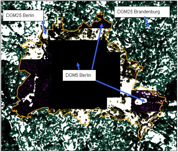
The terrain model was based on a digital terrain model (Digitales Geländemodell DGM5) in the inner city area and, partially, in the north and south-east of the city, while DGM25 was used both for the remaining area and the neighboring area of Brandenburg. The digital terrain models (DGM5, DGM25) describe the terrain in regular grids with a dot pitch of 5 m and 25 m respectively. The terrain model was optimized to remove altitude points which do not contribute to the determination of acoustically relevant terrain structures. The result is a terrain model which consists of heterogeneous altitude points comprised to form a triangular grid (see Figure 1).

Fig. 1: Terrain model based on the optimized DGM25 Berlin (yellow, “non-crowded distribution”), DGM5 Berlin (black-violet, “dense”) and DGM25 Brandenburg (green)

Fig. 1: Terrain model based on the optimized DGM25 Berlin (yellow, “non-crowded distribution”), DGM5 Berlin (black-violet, “dense”) and DGM25 Brandenburg (green)

DGM5 fails to describe the terrain along railway embankments and cuttings satisfactorily. When such structures were located 1 m above or below the surrounding terrain, the corresponding upper and lower edges were determined with an accuracy of < 0.5 m and based on stereo aerial photographs. These edges were then applied to the terrain model as altitude lines (see “Noise Insulation Facilities”). The railroad track network contains altitude data at all track points (see below, “Geometry – Railroad Traffic”). These altitude points were also applied to the terrain model.

Noise Insulation Facilities

_Noise Protection – Road_

The location description of noise insulation facilities at roads was taken from the existing road traffic noise map (data from 1998/2003), i.e. Road Traffic Noise Map 07.02 (edition 2005). Since part of the data was not available in georeferenced format, additional evaluations of aerial photographs and photographs on site were incorporated in the digital system as best as possible. The position and altitudes of the noise insulation facilities at the Federal Autobahn A113 (new) were directly taken from the documents for approval of the A113 (new) plan and incorporated in the digital system.

_Noise Protection – Railroad_

The Bahn-Umwelt-Zentrum of the Deutsche Bahn AG was not able to deliver a location description of noise insulation facilities at railroad tracks. For that reason, noise insulation facilities made of concrete, steel, glass, and the like were determined by means of an external 3D evaluation of stereo aerial photographs and according to the procedure described below. It was assumed that all of the sound insulation facilities were high-capacity sound absorbing noise barriers.

1. Import of current aerial photographs (photographic flight over Berlin in 2006; scanned black-and-white aerial photographs (8 bits); resolution approx. 15 cm) and orientations in the image evaluation system ImageStation SSK from Intergraph.

2. Interactive evaluation of aerial photograph models and entry of the noise insulation facilities in special files:

  • Where noise barriers ( > 1.0 m) made of concrete, steel, glass, and the like were concerned, the center axes were entered as a polygon on top of the barrier.
  • Where embankments ( > 1.0 m) acting as noise barriers (embankment next to the tracks) were concerned, the extension of the embankment was entered as a surrounding polygon.
  • Where tracks are running on top of an embankment ( > 1.0 m above the surrounding terrain), the embankment was entered with its upper and lower edges.
  • Evaluation accuracy: < 0.5 m.

3. Export or import and storage of the differently attributed files to the GIS system used.

Special Structures

_Tunnels – Roads_

In the calculation model, tunnel structures were represented by interruptions in the route sections.

_Tunnels – Railway Stations_

In the calculation model, tunnel structures were represented by interruptions in the line sections. The course of tunnel structures was represented in the layout plan. The level of emissions caused by trains passing through stations was calculated analogously to that caused by trains in the open terrain. Attenuation by platform edges and station buildings was not taken into account.

_Road Bridges_

Bridges across roads and waters were taken into account in 241 areas where the high position of a road has a relevant acoustic effect on the neighboring built-up area. A reflecting bridge platform was modeled across the width of the road in each of these cases.

When using the noise map, the following must be observed: bridge structures are not included in the surface of the terrain; rather, they are rising above the terrain. Noise maps are calculated at a height of 4 m above the terrain and can, therefore, be related to the area below a “noisy” road bridge which acts as a sound barrier with accordingly low local immission levels.

Built-up Area

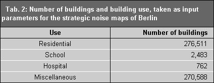
550,344 floor plans of building objects with specification of the number of floors and the following building use were taken from the automated real property map of the City of Berlin (see Table 2):

Table 2: Number of buildings and building use, taken as input parameters for the strategic noise maps of Berlin

Table 2: Number of buildings and building use, taken as input parameters for the strategic noise maps of Berlin

Explicit building heights were not available and were, therefore, defined through the following empirically determined function: [building height = 3.2 m + number of storeys x 2.8 m]. At a distance of 3 km from the urban area, 231,445 buildings with explicit height data from the Land of Brandenburg were applied to the model. These buildings act as obstructions and reflectors of road and railway noise sources in the marginal region of the area under examination.

Building facades were included in the calculations as reflecting with an absorption loss of 1 dB(A).

Building Inhabitants

The number of inhabitants with principal and secondary domicile is available in 14,253 partial areas of the urban area with a total of 3,331,249 inhabitants in 2005 (population density map 06.05 (edition 2006)). These inhabitants were distributed proportionally over the floor areas of the residential buildings located in the particular partial areas. Buildings with mixed use were taken into account with 75%.

Dwellings

The number of dwellings was determined in relation to districts, based on the district areas and the number of inhabitants and households (dwellings) per district, which were taken from the statistical reports “Ergebnisse des Microzensus 2005” (2005 microcensus results) and “Wohngebäude und Wohnungen in Berlin 2005” (residential buildings and dwellings in Berlin in 2005) for Berlin (cf. Statistisches Landesamt Berlin 2005). This results in a mean value of 0.554 dwellings per inhabitant for the entire urban area, with only low variations. This factor and the known number of inhabitants involved were used to determine the number of dwellings involved.

Geometry – Road Traffic

The geometry of the roads under examination as well as the necessary information about the surface and the condition of the carriageway, the allowed maximum speed, the position in the terrain, and the number of lanes were taken from the existing traffic noise map for principal roads (see Road Traffic Noise Map 07.02 (edition 2005)). The data regarding the surface and the condition of the carriageways was reviewed and updated based on information from the districts and on photographs taken on site.

Furthermore, the already implemented speed-30 sections of the principal road network were determined from the existing speed-30 concepts and incorporated in the road network database. Road sections where corrections caused by multiple reflections had to be taken into account were determined based on the density of the built-up area extending in parallel to the road (see below, “Calculation Methods – Road Traffic”).

Sections of the principal road network, which have not yet been contained in the traffic noise map but are a part of the traffic survey network, were photographed on site (surface and condition of the carriageway, speed limit, position in the terrain, lanes, information about built-up areas, noise barrier) and incorporated in the road network database. Sections where corrections caused by multiple reflections had to be taken into account were also determined.

The traffic intensities of the 2005 traffic count were assigned to the sections. The data contains information about the average daily traffic volume (DTV), about heavy traffic and about bus traffic. Calculations according to the VBUS (“Vorläufige Berechnungsmethode für den Umgebungslärm an Straßen” or “preliminary calculation method for environmental noise at roads”) takes heavy traffic with 3.5 tons and more into account.

Additional sections outside of Berlin were digitized based on topographical maps. The figures of the traffic intensity map of the Land of Brandenburg (2002) were assigned to these sections.

A total of 1,770 km of the road network was included in the calculation. 1,362 km of these roads are located in the territory of the City of Berlin.

Geometry – Streetcar Traffic, Above-Ground Subway Traffic

The geometry of the streetcar and the above-ground subway networks as well as the necessary information about the type of rails, the speed limit and the position in the terrain were taken from the existing traffic noise maps for principal roads and railway traffic. The Berliner Verkehrsbetriebe (BVG) provided traffic data on streetcars and above-ground subways of 2006. This data as well as updates relating to the types of streetcar rails were included in the geometry. Altogether, 188 km of the streetcar and 26 km of the above-ground subway networks were included in the calculation.

Geometry – Industrial and Commercial Plants

Plants have an effect on environmental noise if they cause relevant sound immissions at the nearest place of use to be protected, which exceed LDEN = 55 dB(A) and/or LNight = 50 dB(A). The researches has resulted, that only one industrial plant comes within the limits of these values.

The Berlin noise map for commercial locations with an effect on environmental noise comprises 18 power plant locations and one industrial plant (cf. IPPC Directive).

According to an expert opinion of 2005, the Westhafen also causes rating levels at the nearest residential built-up area of less than 55 dB(A) during the day and less than 44 dB(A) during the night. According to the Environmental Noise Directive, the Westhafen is, therefore, considered to be acoustically irrelevant and was consequently not included in the examination.

The geometry for the 18 power plants inside the urban area of Berlin was determined from data about the land parcels allocated in the real estate cadaster and by comparison with the digital orthophotos and the power plant providers. The emission caused by the power plants and the IPPC plant was modeled by means of area-related sound power levels.

Geometry – Tegel Airport Traffic

The following input data was available for calculating aircraft noise:

  • data acquisition system DES 06/2005, actual state of 2004;
  • geometric description of the takeoff and landing runways as well as the approach and departure sections (position, altitudes, flight corridors) and route assignment with activity counts of individual aircraft types;
  • distribution of flight movements of individual aircraft types for day, evening and night periods, on takeoff and landing runways in 2005.

The data acquisition system is not available for 2005. According to the Deutsche Flugsicherung DFS (German Air-Traffic Control), the route descriptions of 2005 did not differ from those of 2004, so that they can be applied to the year 2005. The submitted distribution of flight movements refers to the takeoff and landing runways; there are no details about the individual air routes. For that reason, the distribution of flight movements in 2005 over the individual air routes was applied proportionally to that found for 2004 in the data acquisition system.

Geometry – Railway Traffic

The railway and suburban fast train track sections were prepared by the Bahn-Umwelt-Zentrum Berlin (BUZ) of the Deutsche Bahn AG. The 2006 traffic data (after commissioning of the main station) were assigned to these track sections.

The route network was included in the calculation with a total of 1,365 km, 1,066 km of which are located in the territory of the City of Berlin.

There is no detailed information about areas with small curve radius where the trains do not cause any squealing noise or where such noise can be excluded through technical measures. For that reason, correction values for curve squealing noise according to VBUSch were used systematically on a worst-case basis, without taking the actual occurrence of such noise into account.

Calculation Model

The input data is prepared and combined in a 3D calculation model of the IMMI 6.1 software.

Obstructions

Obstructions, such as terrain edges, buildings and noise insulation facilities, were taken into account with the parameters described in the input data (position, altitude, reflection property, and the like). The basic model formed from the terrain and obstructions remained as it was for the calculation of all noise types.

Determination of Reception Points

At residential buildings, hospitals and schools, the position of reception points was determined according to the “Vorläufige Berechnungsmethode zur Ermittlung der Belastetenzahlen durch Umgebungslärm” (VBEB, “preliminary calculation method for determining the exposure figures caused by environmental noise”). The number of inhabitants in residential buildings was distributed across the reception points of the respective residential buildings in equal shares.

Plausibility Check

The plausibility check consists of a visual check of 3D views of the calculation model and numerous automatic plausibility queries.

Calculation Parameters

Mappings within the scope of the Environmental Noise Directive cannot be achieved in economic calculation times if the applicable calculation rules are to be followed completely and strictly. For that reason, calculation parameters were determined in a simplified manner (minimum level distance = 25 dB(A); range of reflection surfaces limited to 200 m), essentially resulting in a neglection of irrelevant immission effects at certain reception points. As tested and certified, the accuracy requirements for the noise mapping calculation results were met and complied with a total accuracy of 2 dB(A).

Calculation Method

_Road Traffic_

VBUS (“preliminary calculation method for environmental noise at roads”) was used for acoustic calculations of the strategic noise maps (cf. 34th BImSchV, Para. 5, Section 1). The noise indices LDEN (weighted 24-h mean value) and LNight were calculated with a step size of 10 m x 10 m at a reception point height of 4 m above the ground.

The number of persons exposed in their dwellings, of schools and hospitals was determined according to VBEB (“Vorläufige Berechnungsmethode zur Ermittlung der Belastetenzahlen durch Umgebungslärm” or “preliminary calculation method for determining the exposure figures caused by environmental noise”).

The corrections for multiple reflections were determined and considered according to the specifications made in VBUS (“preliminary calculation method for environmental noise at roads”). Separate corrections for traffic lights are not allowed.

_Streetcar and Subway Traffic_

VBUSch (“Vorläufige Berechnungsmethode für den Umgebungslärm an Schienenwegen” or “preliminary calculation method for environmental noise at railways”) and VBEB (cf. 34th BImSchV, Para. 5, Section 1) were used for acoustic calculation of the strategic noise maps as well as the persons exposed in their dwellings, schools and hospitals. The noise indices LDEN and LNight were calculated with a step size of 10 m x 10 m at a reception point height of 4 m above the ground.

+Commercial Plants+

VBUI (“Vorläufige Berechnungsmethode für den Umgebungslärm durch Industrie und Gewerbe” or “preliminary calculation method for environmental noise caused by industrial and commercial plants”) and VBEB were used for acoustic calculation of the strategic noise maps as well as the persons exposed in their dwellings, schools and hospitals. The noise indices LDEN and LNight were calculated with a step size of 10 m x 10 m at a reception point height of 4 m above the ground.

_Air Traffic_

VBUF-DES (“Vorläufige Berechnungsmethode für den Umgebungslärm an Flugplätzen – Datenerfassungssystem” or “preliminary calculation method for environmental noise at airports – data acquisition system”) and VBUF-AzB (“Vorläufige Berechnungsmethode für den Umgebungslärm an Flugplätzen – Anleitung zur Berechung” or “preliminary calculation method for environmental noise at airports – calculation instructions”) as well as VBEB (cf. 34th BImSchV, Para. 5, Section 1) were used for acoustic calculation of the strategic noise maps as well as the persons exposed in their dwellings, schools and hospitals.

_Railway Traffic_

VBUSch (“Vorläufige Berechnungsmethode für den Umgebungslärm an Schienenwegen” or “preliminary calculation method for environmental noise at railways”) and VBEB (cf. 34th BImSchV, Para. 5, Section 1) were used for acoustic calculation of the strategic noise maps as well as the persons exposed in their dwellings, schools and hospitals. The noise indices LDEN and LNight were calculated with a step size of 10 m x 10 m at a reception point height of 4 m above the ground. According to VBUSch, the rail bonus (deduction of 5 dB because of the lower disturbing effect of railway traffic) provided in the National Calculation Provision for Rail Traffic Noise (“nationale Berechnungsvorschrift für Schienenverkehrslärm” SCHALL 03) is not assigned.

Using the Data Display

The various subject maps herewith made available to the public represent the noise situation in relation to areas in a classified form, as provided in the Environmental Noise Directive. What is more, they also provide the possibility of polling factual data: maps 07.05.1 to 07.05.10 display the individual grid values forming the basis of the classification and, for road traffic noise, additional background information about the principal road network registered. Since the grid used for representation in these maps is a 10 m x 10 m grid, the individual statements are not suited for precise evaluation of buildings. For that reason, map 07.05.11 (facade levels at residential buildings within the exposure range of main noise sources) provides a complete overview of the reception points used on the facades of residential buildings, including the immission levels calculated.